


Part 2 of our “Let’s Build a Train!” series deals with building the wheel or “truck” assemblies for the GP38. One of the truck assemblies drives the train using the gearbox we previously built. Depronized (Designer of the GP38) did an excellent job of creating such an awesome engine. You can find many of his designs on Thingiverse.com
However, we were unable to locate the type of O-rings he used for the GP38. So, we had to come up with our own components to work with his drive truck assembly so that we could use commonly available O-rings from Harbor Freight.
Let us continue building our train!
Here is a list of things you will need:
- Depronized’s GP38. You can download it here .
- Some PLA filament. We used Solutech Silver Metal

3. Some 3mm brass rods. We used these

4. Eight bearings of this type. We used these
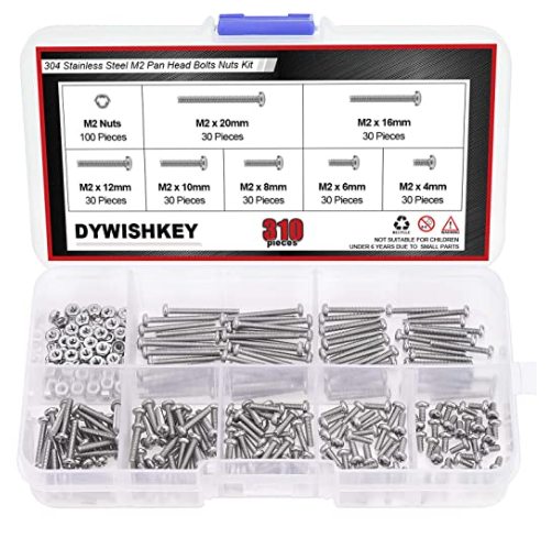
3. M2 sized screws (4mm and 12mm in length). We chose this one from Amazon because it gives us a good assortment
4. M3 screws

Or these

- Harbor Freight O-Ring assortment. We used the metric assortment, item 67609.

- Our wheels, axle drive gears plus other components for the GP38. You can download it here.

Download: GP38 Truck Parts
1 file(s) 163.69 KB
Getting Started Building the Rear Truck
The first thing you should do is print out a mixture of components. You will need to first print out our drive wheels, axle drive gears, and drive axle spacer. We recommend using 100% infill as most of these parts will be taking some abuse and stress (Just like the gear box) So you want to make them as tough as possible.

Next, you will want to print out some of Depronize’s original truck components. From the drive truck, you will only need these components:

Again, we recommend printing these parts at 100% infill to make them as durable as possible.
Tip: When you print out Depronize’s truck, if your slicer software supports it, you might want to add a single support here where the bearing will go. This will help you fully install the bearings properly later.

Preparing the Drive Wheels
To prepare the drive wheels for mounting you need to install an O-ring on each wheel. The O-rings we designed our wheels for are the metric O-rings they sell in an O-ring kit called Nitril O-Ring Assortment. The P12 (11.8 x 2.4mm) O-rings in that kit are perfect for our wheels.

The O-ring will slide easily around the wheel. Make sure it is fully seated evenly all the way around the wheel. You can do this by using a small, bladed screwdriver to push against the O-ring as you rotate the wheel.

When properly seated, the O-ring will be just about even with the outside edge of the wheel. Do this for all 4 drive wheels.

Once the wheels have been prepared, you need to prepare the main drive truck to receive them.
Preparing the Main Drive Truck
The main drive truck consists of Depronize’s original components a brass drive shaft and two bearings.

For the brass shaft, you will need to cut it exactly 42mm long. Any longer or shorter and your parts will not fit correctly.
The first thing you need to do with the truck is to press the two bearings into it at the points indicated here.


You really want to make sure both bearings are as fully seated as possible. You may have to press these in using a C-clamp.

Installing the Main Drive Shaft
To install the main drive shaft, you first must press on this gear to the shaft:
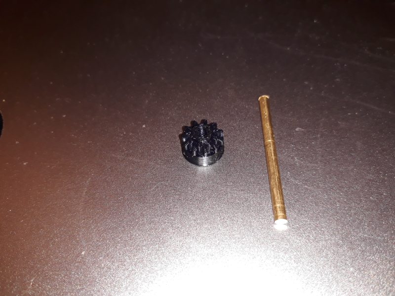
The gear should be flush with the end of the shaft. Once installed, it will look like this:

You can set this aside for the moment. You now need to install the shaft retainer on the truck.
Installing the Drive Shaft Retainer

To install the drive shaft retainer on the truck you will need a couple of M2 x 4 screws. Install the retainer as shown on the truck.

Once the retainer has been installed its time to add the main drive shaft. To do this, you need to slide the shaft into the end of the truck which only has the bearing, so the end of the shaft without the gear comes out the side with the retainer like this:

Now comes the tricky part. You need to install the other drive gear on the end of the shaft. It is this gear:

This gear, like the other one, is a very tight fit, and you probably will have to press it on. But the problem you are likely to run into is the same one we had. Once you press it on flush with the shaft, you may find that the gear is not all the way back as in needs to be, like this photo shows:

You will notice in the photo the gap between the retainer and the gear. The gear will not work this way, as it will not properly engage with your gearbox you previously built. To get the gear on the rest of the way, you need to become a bit creative. So, we will explain what we did.
We located a socket with a drill bit adapter and installed it in our drill press. This allowed us to press the gear on the rest of the way. We just lined up the socket with the end of the gear and pressed it on. Here is a photo generally showing what we are talking about, right before we lined up the socket with the gear:

We also used a small block (in this case aluminum) to just press against the other end of the gear (and not the truck, to protect from breaking it. When its all done, the position of the gear now looks like this:

Now you are ready to move on to assembling the drive wheels and gears.
Assembling Drive Axles with Wheels and Gears
You will need the drive wheels with installed O-rings, your axles, (which you need to cut 44mm long) and our drive gears to create both assemblies:

Here is an easy way to assemble each one if you have a drill press or something similar.
First place your shaft in the drill press like this:

We used a small block below the shaft with holes in it. This makes it quite easy to line up and insert each part.
Next you want to install your first wheel.


Once you have the wheel on the shaft, you should be able to slide it up to the chuck of the drill press with a little effort.

At this point, you can proceed one of two ways. You can install the gear (which is next) or you can choose to also install our axle spacer. We recommend doing this on one of the shafts, specifically the one that will be installed on the rear axle. The reason for this, is after our initial assembly, we found that this axle is always torqued sideways when the engine runs, causing the drive wheel to be pushed in. The spacer prevents this from happening. If you choose to do this, you will want to install this next, before pressing on the gear. Here is a photo showing the spacer in place:

You need to line up the drive gear with the gear teeth facing the wheel you just installed before pressing it on:

Press the gear on but stop after you expose a small portion of the shaft. You need to press the other wheel on so that if faces down and the back of the wheel faces the gear. It will butt up against the gear. Only press the wheel one until a small portion of the shaft is exposed.

Here is what your finished wheel assembly will look like:

Repeat the process for the other assembly.

Note: our photo above does not show the spacer we earlier described. Now you are ready to move on to install the assemblies in the drive truck.
Installing the Axle Assemblies
The axle assemblies now need to be test fit in the truck to make sure you have enough room for the bearings to be installed.

If you have properly spaced your wheels and gears, the gears will mesh with the drive axle you previously installed. Also, the wheels will just clear the inside edge of the truck. If you need to make any adjustments, now is the time to do it. After you are satisfied, its time to install them with the bearings.
You will need 4 bearings to slide on to the axles, two for each.

Slide a bearing over the end of each axle and press them into the truck. They should go in easily.

This completes the assembly of your truck. You should be able to rotate the wheels and see all the gears mesh smoothly at this point. If not, look for burrs or adjust the gears on each axle until they rotate smoothly. Your ready to move on to attaching the truck connector
Attaching the Truck Connector

The truck ball connector joins the truck to the rear chassis. This connector needs to be installed on the truck before you can attach the gearbox. To connect it to the truck, you need an M2 x 12mm screw
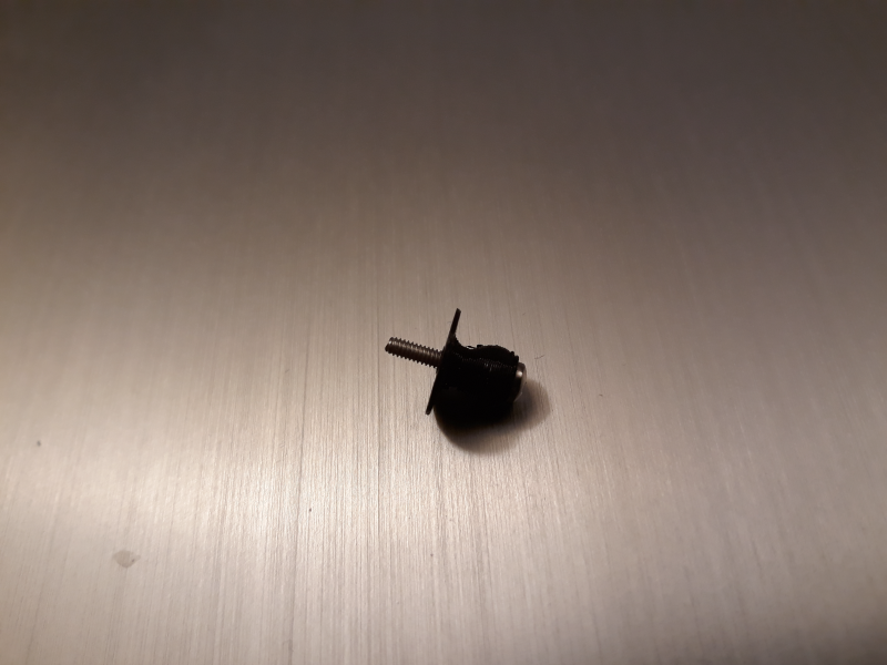
You first need to thread the screw into the nub first all the way. Then screw the assembly into the truck.

Connecting the Gearbox to the Truck
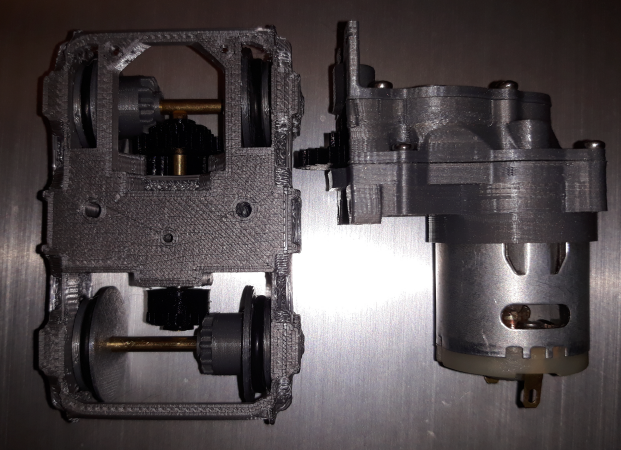
The final step to completing your truck is to attach the gearbox motor assemble to it. The gear box is oriented they way you see it here. But how does it actual “fit”?
The larger portion of the gear sits in this trough:

What actually “meshes” from the gearbox with the lower gear is the smaller portion of the gear from the gearbox:

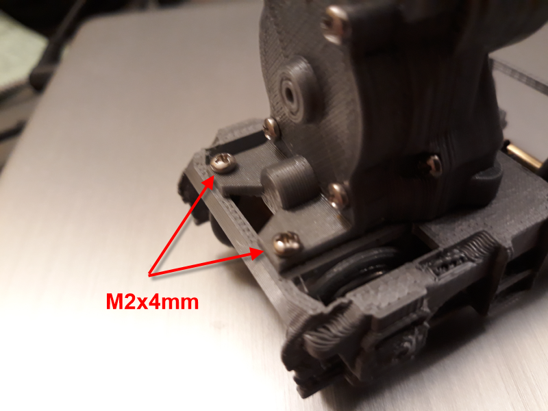
You need to line these two up when you place the gearbox on top of the truck. Once you do, the holes at the end of the truck will line up with the ones at the end of the gearbox. You can secure the Gearbox using two M2 x 4mm screws. This will align the gearbox so it can be secured by the main screws that you need to install from underneath the truck.
You need to be careful at this point not to break the gearbox mounting you have just secured. Turn the entire assembly over.
The main screws you need to fully secure the gearbox are two M3x16mm long screws.

Install these in the holes under the truck.
Tip: As you begin to thread each screw in, you may have to press and hold the gearbox in place until the screw starts. If you see it start to push the gearbox up, stop, back the screw out slightly, and try again. Otherwise you may break the gearbox mount.

Your rear truck assembly is complete!

Assembling the Front Truck
Assembly of the front truck is straight forward and you can use all of Depronized’s components.

You will need all his parts, plus two more axle shafts and four bearings.

You will need to press on the wheels in a similar manor to what you did with the rear wheels. The main difference is these spacers properly space the wheels for the track. If you do not want to use the tight-fitting spacers, we have included two other different ones for you to try in our download. One of them is much thinner but performs the same function.
After you are satisfied that you have equal amounts of shaft protruding on each axle, you can install them using the bearings.

Place the truck mounting block in the center of the truck as shown.

Two M3x12mm screws secure the front truck to the block that connects to the front lower chassis.

That is it! Both trucks are now ready to roll!

We hope you have enjoyed our “how to article” on building the trucks for the GP38. Please stay tune for the next installment where we will cover both lighting and the electrical components of the GP38 build.